
Three Greatest Moments In Fuse Box Installation History
 Important Aspects of Electrical Installation Testing
Regular inspections and testing of electrical installations is vital. They can become less reliable with time due to age and wear. This ensures that your premises are secure and minimizes the risk of fire.
A qualified expert is required to conduct the test using all the necessary equipment. They will issue you with an EICR (EICR) that serves as evidence of the maintenance of your electrical installation.
Voltage
Voltage testing is a crucial element in the testing of electrical installations. It can detect voltage in wires, wires and circuit breakers, and light fixtures. It also helps verify that a device is functioning correctly.
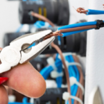
Testers and meters are diagnostic tools that measure the electrical current, voltage, and the polarity. They can help you locate hot wires or receptacles. They can also check for requirement for Electrical installations ground faults and determine the type of wire connect.
Multimeters also allow you to detect an erratic voltage. This is the voltage that isn’t related to neutral or ground wire. It can be caused by capacitive connection between wires not connected or an open connection.
This type of strayvoltage is often confused with energized electrical energy. It should be immediately identified and corrected. It can cause damage to your equipment and increase your chance of being injured.
A hipot test is utilized to determine if the flow of current will not be from one place to the next if it were plugged in (and to turn up the voltage very high to make sure that it doesn’t). Only electrically certified workers are permitted to test hipot testers to test supply lines that are single or three-phase.
First, isolate the circuit or Cable to be hipot test. Barriers around terminations are utilized. At 1000 volts the limit of the approach is 5 feet. The ground wire of the hipot tester should be connected to an earth or the grounded electrode conductor of the isolated circuit phase conductor.
Insulation tests are a series testing the resistance of the product to direct current flow from an external voltage source. They are typically conducted by using an insulated device that can deliver a no-load voltage of 500 V or 1000 V if the nominal voltage of the insulation system is higher than 500 V.
These tests are usually performed on high- and low-voltage components such as circuit breakers, transformers switchgears, cables, and lightning arrestors. These tests are conducted according to the specifications of the relevant safety standard and are usually used as part of an overall inspection procedure.
Current
The current test involves the use of a meter to gauge the resistance of an electrical installers near me circuit. This helps to check that the circuit is connected properly and will not break when a certain voltage is applied. This can be done by either observing a light/buzzer in connection with the circuit or by measuring the resistance between two points.
Continuity tests are the most popular kind of current test utilized in electrical installation testing. The tests can be carried out in both qualitative and quantitative ways, however they are best done by a qualified electrician.
It is important to remove all switches and outlets from the circuit to conduct continuity tests. This ensures that the test is carried out correctly and safely.
It is vital to remember that ring circuits must be tested correctly. Incorrect polarities could cause parts of an installation to be connected to a live conductor even in the event that single-pole switching devices have failed or over-current protection devices have been turned off.
An ohmmeter equipped with the continuity function can detect the wrong polarity. An experienced electrician can use it to detect it. The ohmmeter must be set to a low level, and the tester ought to be placed between Line and Earth terminals at each outlet of the circuit.
A qualified electrician should verify that all conductors used for protection including the main and additional equipotential bonding, are connected to the supply earth through the testing of the main earthing terminal as well as the ends of each conductor.
The earthing system is a crucial element of electrical safety. It sends electricity to the ground. It protects both appliances and individuals from electrical surges and shocks.
Before any equipment that is permanently wired is placed into service, it what is electrical installation vital that they are thoroughly examined and tested. It is essential to follow the IEC 60364.6.61 testing procedures, which includes the use of safe clothing and the right testing tools.
Insulation Resistance
Insulation resistance is an important aspect of electrical installation testing, and a indicator of the quality of insulation in wiring and equipment. It helps avoid dangers such as electric shock and short-circuits by making sure that electrical wires and equipment are well-insulated.
It is vital to regularly check the state of insulation in equipment and wiring to prevent the breakdown of equipment and wiring. The durability of insulation can decrease as time passes because of environmental conditions such as temperature, humidity, and moisture.
Insulation that has been damaged over time can weaken and less effective at preventing the flow of electricity. This can cause overheating, electric shock, and fires.
To prevent this test, a range of tests are conducted to test the condition of insulation in domestic electrical installation wiring and equipment. These include proof tests, spot reading, time resistance and step voltage.
Proof testing involves connecting an Megger instrument to a piece of equipment, and then operating the meter requirement for electrical installations; 45.viromin.com said in a blog post, a predetermined period of time. The meter then displays the resistance values on the display and record the results of this measurement.
It is also possible to test insulation by using the spot reading method. Simply connect the Megger instrument and operate the device for around one minute. The meter will display the resistance values on the display and you can note them down at different times.
This is one of the most effective methods to record insulation data because it offers the ratio of two time-resistance readings. This ratio can tell you whether the resistance is increasing/ decreasing over time, and provide a good indicator of the condition of your insulation.
Another method to measure resistance is to use the polarization index. It is the value of the resistance measured at 10 minutes to the resistance value at 1 minute, and any value that is lower than 1.0 indicates bad insulation. A PI between 2.0 and 4.0 is considered good insulation, while anything greater than 4.0 is excellent.
Earth Resistance
Testing for Earth resistance is an essential component of electrical installation prices installation testing. It ensures that the grounding system functions properly and protects people and equipment from excessive voltages. It also helps to identify any issues in the grounding system prior to they become serious.
There are a number of different test methods available for measuring earth resistance. They include fall-of-potential tests touch and step potential tests as well as earth coupling tests.
The most commonly used and reliable method is the fall-of-potential test. This is a well-established test method that is founded on IEEE standards and is suitable to determine the resistance of transmission lines.
It involves placing an electrical installers near me voltage spike and a electrode for testing current in the soil at different distances along the straight line. The current is then measured at every distance and the resistance of the electrode under test is calculated using Ohm’s Law.
This test method is a fantastic method to determine the soil’s resistance at different depths however, it is vital that you perform this test correctly. The soil’s composition and the amount of moisture can affect the results you receive So, make sure you be aware of this before choosing the layout of your earthing system.
A stake-less method is a different method of testing earth’s resistance. This method uses a tiny test device that connects directly with the ground electrode and not a clamp-on tester. This is a great option for a variety applications, including remote switching offices as well as cellular towers.
Stake-less tests can be conducted on various surfaces, so they are suitable for a wide range of applications. However, it is crucial to keep in mind that they’re not a real test for measuring ground resistance , and should not be used in place of a fall-of potential method.
The most widely used method for testing the earth is the fall-of-potential method which uses an electrical voltage spike and an a current test meter. The voltage spike is inserted in the soil at various distances and the current is measured at each distance. The voltage drop and current through the electrode are used to calculate the resistance.